 /AUTOGAINE: Design air conditioning networks
Faster air conditioning networks
design & installation with AUTOGAINE
AUTOGAINE
Faster air conditioning networks design.
Calculate, design and quantify:
- Circular ducts
- Rectangular ducts
- Smoke exhaust ducts
- One-line or two-line mode
Use the apertures and accessories implemented in the HVAC installations.
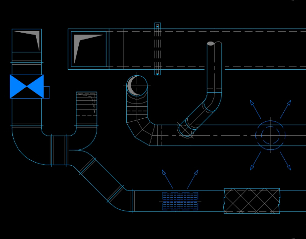
Smart routing of air conditioning networks with AUTOGAINE
Save time and simplify the job of designing your air conditioning duct networks using AUTOGAINE smart routing. The application intuitively proposes the most pertinent design options as the routing process advances.
Objects are created on demand as the lines are drawn thus avoiding all the endless searching though component libraries. The objects you need to design even the most specific networks will always be at hand.
Main features:
- Point to point routing for one-line or two-line aeraulics networks.
- Detailed design of all accessories depending on their configuration.
- Automatic component insertion: Tee, connector, elbow, reducer, sleeve, etc.
- Grill and distributor design.
- Detailed flexible duct design.
- Network detailing: flocking, heat-proof, arrows, texts, proprty tags, dimensions, etc.
Modify parts of your air conditioning network in 2D without re-drawing
Adjustment to existing ducts is even faster than for the original outline. The “Change” control, detects the network that has been outlined and then allows one object to be exchanged with another from an intuitive pre-selection.
Change the size of a sub-section or replace one connection with another in just one operation. For example, if you move a branch the connector will adapt to suit. In the same way if you remove a non-return valve, the duct will “close” automatically.
Insert simplified texts
AUTOGAINE pre-programs and pre-formats your text. By clicking on an already existing network, certain items of technical information (such as the cross-section) will be recognised and used automatically.
The application automatically inserts text prefixes and suffixes. The cross-sections will be formatted to suit the specification. These features also include:
- The creation of single or multi-line text
- Automated line number selection
- Automatic tracing of extension lines, frames, arrows, points, etc.
- If the text is modified the extension lines and frames are adjusted automatically
- Font and size selection
- Automatic scaling
Day to day efficent calculations for heating network design
AUTOGAINE offers a range of calculation engines to meet the day-to-day needs of engineering practices in the field of air conditioning and ventilation.
- Spot duct size calculations, according to velocity constraints or geometric constraints.
- Calculation of the coefficients of friction (J) of the proposed duct sizes.
- Dynamic calculation of network sizes in a diagram.
- Calculation of levels while routing the network, after the duct sizes were changed.
To go further, AUTOGAINE gives users the freedom to refine claculations according to their specific needs.
Dynamic duct size calculation :
“Network calculator”
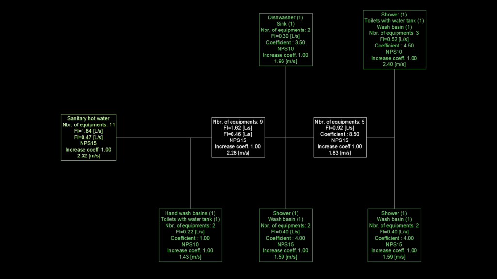
The “Air Network Calculator” commands in AUTOGAINE use a visual method. It makes it easy to calculate sections from an interactive diagram of your network. This clear, concise diagram contains all the information you need to design the 2D plan of your air conditioning and ventilation networks.
With this method, the design and drawing only take place once the data has been worked out with the network calculator.
This process saves you from having to design, claculate and then re-design, according to the results of your calculations. As it is often the case with 3D software.
The Network Calculator is a lightweight yet powerful tool that allows you to dimension networks of any size using a simple network calculator diagram.

Size your networks in an instant
- Draw a simple diagram of your network with the Line command of your CAD software.
- Specify the equipment to be fitted at the end branches.
- AUTOGAINE calculates the duct sizes of each branch immediatly.
- You get a dynamic calculation diagram where AUTOGAINE immediately recalculates when you make changes, try and compare with different equipment or change the network structure.
Quicker with every operation
The detailed analysis of working experiences in design offices has revealed a multitude of opportunities to simplify and accelerate the production of quality design and technical plans.
Here are just a few examples:
- Show a two-line or single-line network crossing by “hiding” or “cutting with offset” one of the ducts in just 2 clicks.
- Recover the impact from one level to another
- Automatically rebuild a duct after cutting
- Practical operations on layers such as freezing, transfer or locking
- Simplified measurement in relation to your CAD software
- Proportionality factors
- Thickness management, etc…
Clear and precise bills of equipment
- Creation of a zone to define the network and material quantities
- Automatic and immediate extraction of conduits quantities within a pre-defined zone
- Automatic and immediate extraction of materials within a pre-defined zone
- Export lists from your AUTOGAINE air conditioning networks to AUTOCAD or EXCEL
- Automatic management and insertion of assigned blocks.
Automated drawings of openings
.
- Design of openings in floor-slabs or walls
- Creation of openings based on completed network designs
- Creation of openings without a network design
- Selection of opening forms
- Automatic measurement of openings
- Location definition and automatic incrementing of the location reference
- Opening design update by modifying its label
- Opening nomenclature extraction with export to AUTOCAD or EXCEL.
Perfect air conditioning networks plan layouts
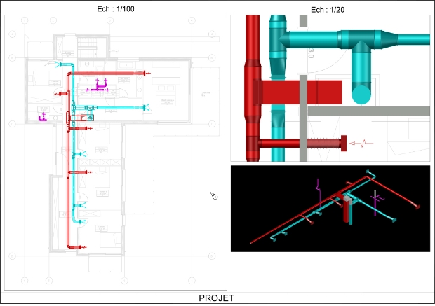
Automatic and immediate page layout for diagrams with generation of presentations:
- Automatic format and label insertion
- View creation with automated scaling
- Rapid insertion of bill of equipment tables
- Simplified modification of existing view scales
- Automatic margin notes including file name and location address along with the XREF associated with the file.
Arrows
Vertical ducts:
- Automatic insertion and placement of arrows indicating floor penetrations and fluid direction
- Automatic modification of arrow directions
Horizontal ducts:
- Indication of fluid direction
- Indication of slopes
Dedicated layer management.
Complete configuration setup of AUTOGAINE for even greater productivity
The default AUTOGAINE setup is being continually refined as the application develops and benefits from years of operational experience. However each user and design office has their own specificities of course. For even greater speed, the application can be configured in every way imaginable. Such as:
- .DWG file preference recognition (when your .DWG file is opened, the corresponding file preferences will be automatically loaded along with the management of the most recent changes)
- Working units
- Line scale
- Layer names and colours
- Configurable line types
- Hatching types for coatings (heatproof, flocking, slab, etc.)
- Automatic configuration of TP scales and management of the shift from object space to paper space (can be automated but not obligatory)
- Design and calculation unit settings
- Graphic appearance settings
- And many other user setting possibilities.
Easy and secure plan background processing
AVANT/APRÈS application du paramétrage
- Entity colours
- Layer colours
- Z coordinate zero reset
- Isolate text, hatching, dimensions…
- Text font processing
- Smart layer re-naming for easier sorting
- System management (Metric/Imperial)
- Management of line thickness, TP scales, etc.
BEFORE/AFTER processing application
Layer management
Even greater layer management flexibility for your project. All layer names and structures are possible. With this, AUTOGAINE optimises management:
- By speciality, depending on the one-line or two-line representation mode (highly flexible).
- Depending on graphic entity type (networks, materials, etc.).
Different layer associations are possible to save time.
Graphic variables
Each designer has their own personal touch, and this is often the sign of genuine know-how. AUTOGAINE’s graphics variables can adjust:
- Representation of the appearance of the ducts.
- Representation of texts, measurements, arrows, duct intersections.
Proportionality management depending on the output scale to provide even greater legibility. Such as:
- Smart adjustment of vertical duct diameters
- Adapted line thickness
- Arrow sizes
- Improved radiator thickness representation
- And many other graphic settings.
Calculation variables
Take your calculations even further with refining variables:
- Rectangular/circular cross-section conversions.
- Material friction coefficients.
- Flow-rate units, pressure loss units.
Know AUTOGAINE like the back of your hand
 AUTOFLUID INFINITY new developments